I am listing here the components that the Great Whyte Clock in Ramsey would have needed to make it work in 1888. Some of these I have found in descriptions from Newspaper cuttings of the original specification and the rest has come from my research on Victorian pendulum clocks. The true workings of the clock is still a mystery, We know that the water paddle that entered the River would have only wound up the weight, which then drove the pendulum mechanism. How the weight dis-engaged when the weight was fully wound up and then re-engaged when it had fallen to its minimum permissible level, we do not know!
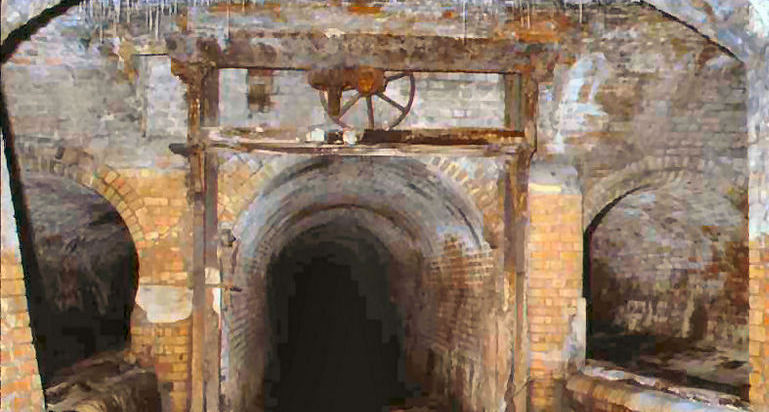
This photo shows the chamber where the clock water paddle was fixed onto the gear wheel shown, down into the river, this would then have turned the big wheel which had around it a 30ft long piece of looped steel wire which went along the tunnel through small pulley wheels up into the base of the clock column.
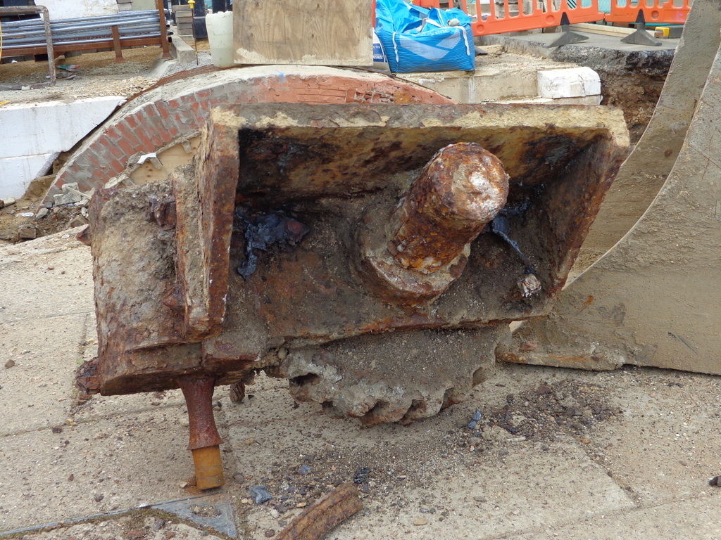
Showing the back of the Gear Wheel
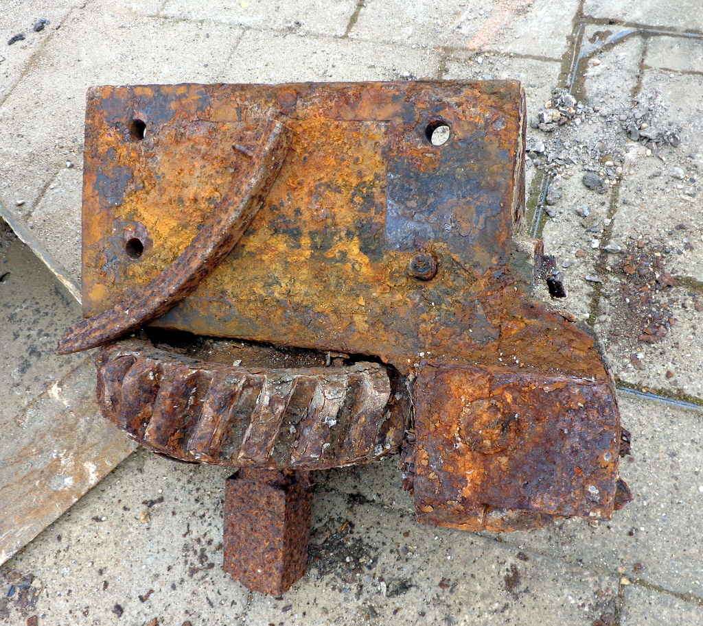
These photos show the gear wheel that drove the paddle wheel which was immersed the river below. These still existed when the repairs to the Chamber shown had its roof repaired in 2016.
Unfortunately we were unable to recue them so they have disappeared forever.
Showing the front of the Gear Wheel
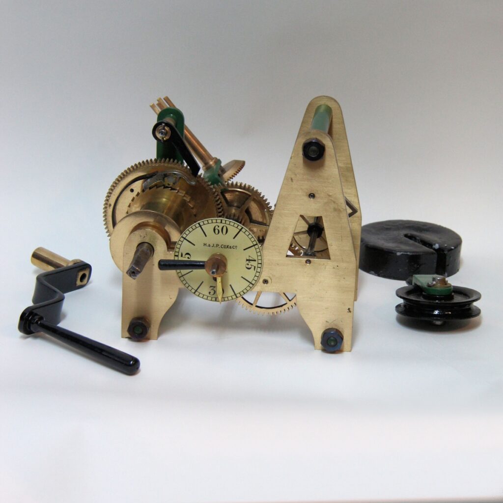
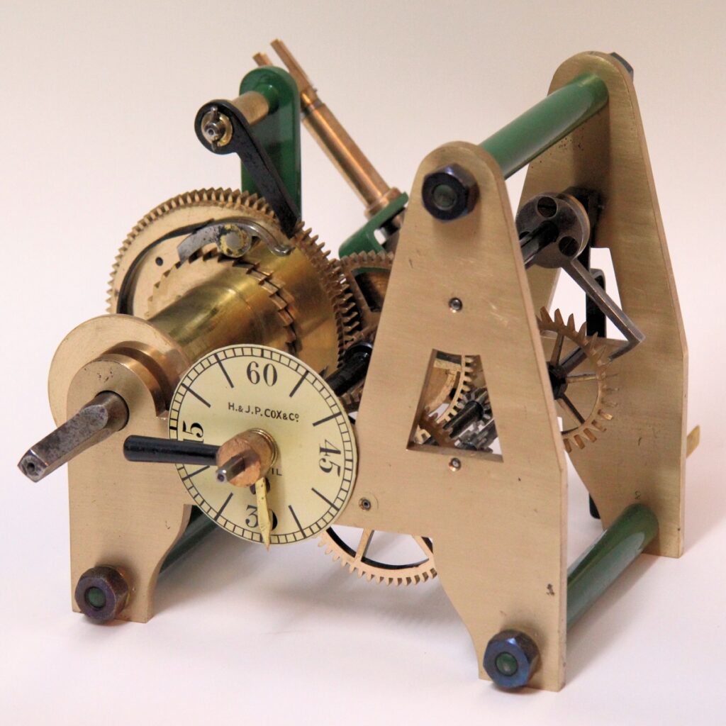
We know that the clock mechanism was fixed in the base of the clock column, because it is written in a newspaper article dated 1888. We currently don’t know how big this movement was, but it had to be a small version of a turret movement.The photos shown below shows us how small and compact a movement could be built. This movement can actually drive the hands of a two foot dial clock face, the Ramsey clock had two of these dials!
This Turret Clock Mechanism shown, measures 11″ deep(total) x 7 1/4″ high x 9 1/4″ wide. I have included it to give you some idea how small these movements could be made.
This Turret Clock dates between 1878 to 1925.
I believe something on the same lines would have been made specifically to fit in the base of the Memorial Clock, space being limited, by the London makers Messrs. Sainsbury Bros, of Black Horse Lane, Waltham, London. This company was a prestigious Clock maker in London from 1734 -18–, they owned a steam driven factory according to their Catalogue and were famous for the Great Mechanical Striking Figure Clock at Sir John Bennetts, Cheapside, London. This suggests that this Clock Mechanism at Ramsey was not cheap to make, we are even told that Mr Sainsbury Senior, fixed the Clock Mechanism and faces of the clock at Ramsey himself, that being the usual custom of the firm.
The clock was using the latest techniques, the movement was fixed in the base! and was connected to the two 2ft dials above using a shaft with improved universal joints. The pendulum was a compensating type beating true seconds, this means that the pendulum length automatically changed when the air temperature changed and kept the pendulum bob at the same height. This was necessary to keep the clock accurate in its time keeping, because if the pendulum lenghthened in the summer due to heat expansion the clock would slow down and if it shortened in the winter due to the cold it would speed up! The most common pendulum length in quality clocks, was the seconds pendulum, about 1 metre (39 inches) long, this gives the time of 1second every swing.
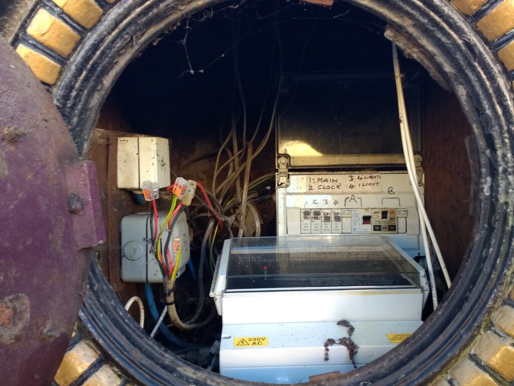
This, I think, would fit the dimensions of the clock base very well, there is at the moment a wooden base for the electrical power units to sit on. When the clock mechanism was originally fixed it would have sat on such a base and a slot would have been cut for the 1 meter long pendulum to drop through into the lower base to swing freely. The wires from the water driven paddle below in the tunnel would have come up through this base too to wind up the weight to drive the the driving mechanism which powered the pendulum and escapement.
Everthing I have described is my interpretation of what the clock mechanism would have looked like and how it possibly worked, unfortunately we have no written information confirming any of this, apart from the sketchy newspaper descriptions of the time.
Looking inside the Clock Base showing the Electrical power Units
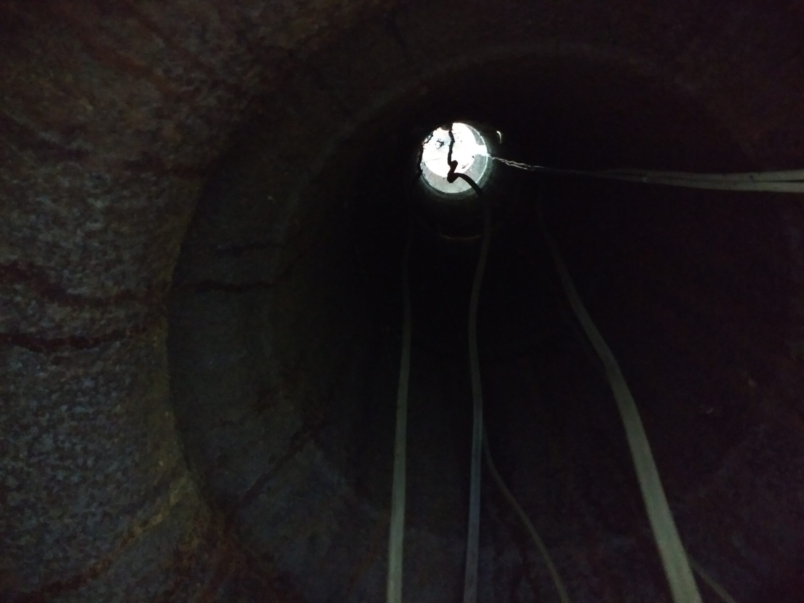
Looking up the Clock column towards the Clock Faces
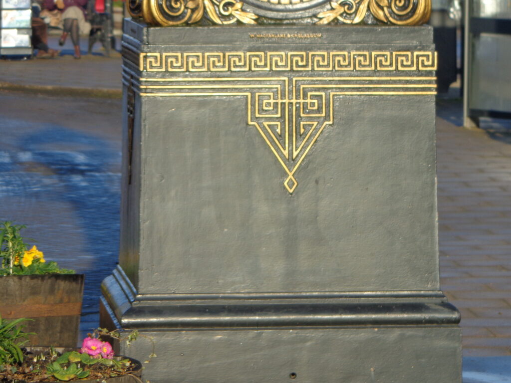
Where I think the pendulum would have swung freely
Showing a Pendulum swing action
The two animations show the way a pendulum acts on an escapement wheel which then drives the clock. It also shows a photo of the actual pendulum Bob that was attached to the end of the pendulum of the Great Whyte Memorial Clock. You can see this at the Ramsey Rural Museum.