Construction of the Culverts
The construction of the Culverts are completely of brick, these bricks are handmade and are approximately 9”x4”x3”, although these measurements vary slightly, they are heavy and do not have a frog in them. There are some wedge shaped bricks too, these are 9”x4”x2”top and 1¾”bottom, these were used as key bricks in the top of the arch.
The main Culvert starts from under the NAT West Bank where the entrance is, and this first section is approximately 400ft long. This ends in the southern side of a big chamber, 25ft x 12ft near the Fellowes Memorial Clock.
Chamber
On the North side of the Chamber the main culvert is joined by the two side lateral culverts, and they all continue down to the Mill end of Town, where they exit. The main culvert measures 10ft across and 10ft in height, externally, and is 2240ft long. The two side lateral culverts are 6ft across and 6ft in height and are 1800ft long.
The roof arch of the main culvert is 15” thick and the two supporting walls are 18” thick (according to the Architects drawings). This leaves a 3” lip on the inside of the supporting walls, for the sole purpose of supporting the wooden arch former when it was being used to construct the arch. The floor is also brick 9” thick and is curved in section, this is to speed the water flow through the culvert.
The former was a curved wooden arch built to the dimensions of the roof span needed (the photo below is a modern take on the former mentioned)
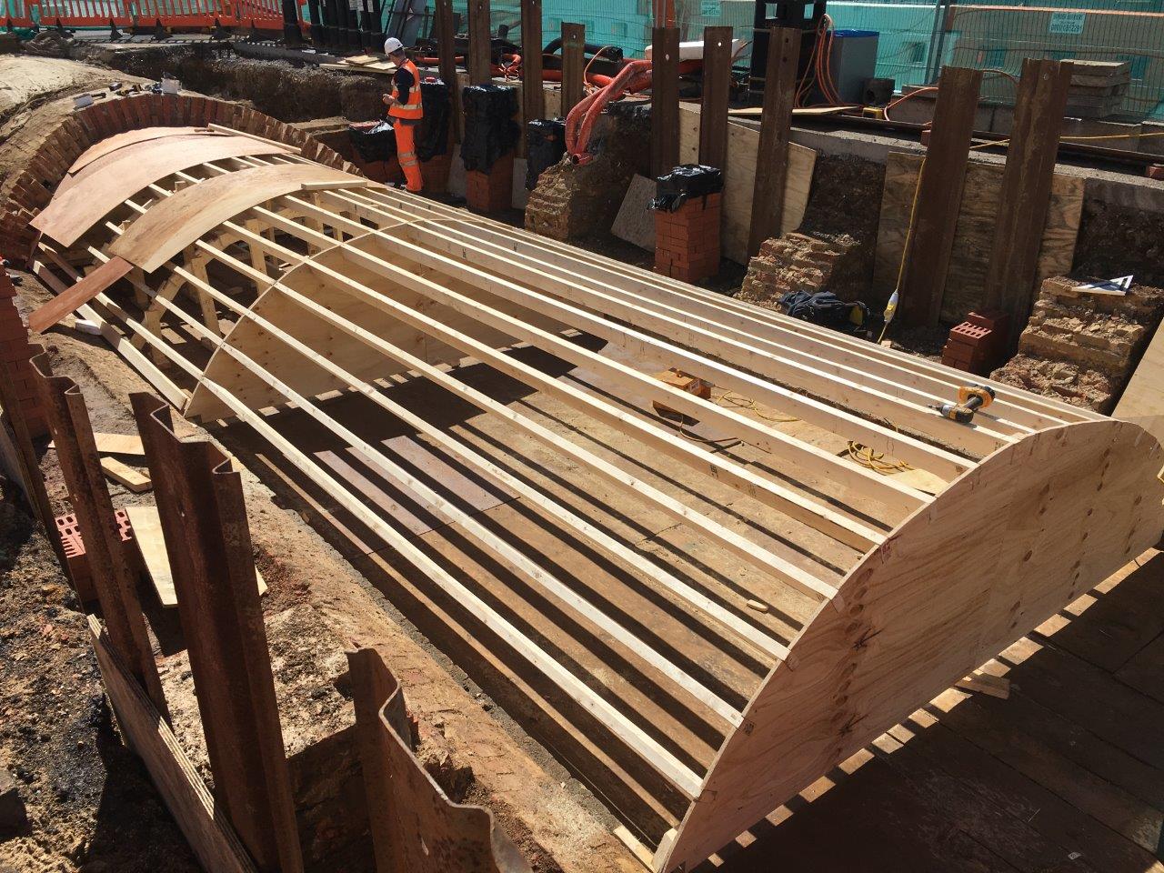
Modern Wooden Former
and would have been at least 8ft long. This, when in use, was wedged up slightly on the 3” lip to support the arch bricks, which were laid over the former from one supporting wall to the other, until the mortar had dried. The wedges would have been removed, which would allow the wooden former to drop away from the brick arch, then it would have been pushed along until it reached the end of the brick arch section. This process would then be repeated over again and again for the whole length of the main culvert.
The roof arch of the main culvert, over the 2240ft, uses approximately 416,000 bricks and the two side walls for the full length 512,000 this does not take into account the side buttresses used to give support to the main culvert from the NAT West bank to the main chamber under the Jubilee Clock, or the main chamber itself. The floor uses 149,000 bricks for the full length. So for the main culvert we have 1,077,000 bricks used, then we have to add the chamber bricks and the extra buttresses.
Side or Lateral Culverts
The two smaller side culverts, were added to help in the time of flooding, by taking the strain off the main culvert and could also be used to take sewage and drainage from buildings on either side of the river. They are 6ft across and 6ft high internal measurements. The brick walls and roof arch were 9” thick. The shape of these side culverts are almost circular. Once again the floor was 9” thick and curved to help water flow. So this culvert is 74 bricks in circumference and allowing 2 bricks in the 9” thickness x 4 bricks in a 3ft length that means there are 592 bricks in that section. Multiply that by the length of culvert 1800ft equals 355,200 bricks times two means there are approximately 710,400 bricks in total in the side tunnels.
Below shows the Architects drawing for the culverts looking North towards the Mill, in the main chamber, and a photo of the actual same place.

Architects Drawing of Chamber
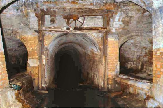
Photo of same place
The culverts start, one either side of the main culvert, from the chamber and continue down to the Mill. Looking at the minutes of the Vestry meetings it would seem that this is where the breaches in the main culvert had taken place, twice in the first 14 months of building, which caused flooding and damage to properties in 1852/3.
This is why the Architect Mr Allen from St Ives, came up with the plan for adding the two side culverts to take the pressure off the main Culvert under extreme conditions. You can see the small side walls one either side of the main culvert, these are designed to let water flow over the top of them into the side culverts if the water level gets to high. Helping to reduce the pressure in the main culvert.
1852
The river bank line shown below on a copy of an engineering drawing by Mr Allen from 1852 it shows the river banks measured approximately 33ft from one side to the other at its narrowest point.
Architects Drawing of Culverts and River Bank line
In the 16th century two lodes (rivers) flowed into the North end of the Great Whyte, Bill lode and Highlode. They are represented on the LIDAR map below as white lines in a Y shape. A LIDAR map is built up by an aircraft which when flying overhead fires a Laser beam down onto the ground below. The resulting map shows the different heights of the land above sea level. All the blue area shown below is at sea level, while the black shape of Ramsey island is at its highest point about 29ft above sea level. The large green area is around 60ft above sea level. This shows you how low the Fens are and why they were prone to flooding in the past.

LIDAR Map of Ramsey Island
The Bill lode was filled in sometime in the late 1840’s. Due to the drop in water level, caused by new drainage channels that had been cut to stop flooding in the Middle Level. Later on in 1850 Whittlesey Mere was drained this also had an impact on water levels through Ramsey as well.
By looking at the present Highlode river which flows in at the North end of the Great Whyte, we can estimate that the original river flowing through the Great Whyte in 16th-19th century would have been comparable in size which varies between 18-25ft today.